24v Dc Motor Control Circuit Diagram
Dc motor circuit control diagram speed electrical using controller forward wiring simple source Control motor dc pwm circuit small diagram using controller electronics nte op amp gr next Brushless bldc 555 timer circuits sensorless ne555 how2electronics
24V DC motor controller with 20A Shot Circuit Protection
Dc motor control using thyristor 3hp 220v inverter phase circuit regulator Motor circuit 20a protection control speed mosfet driver shot dc 24v controller 24vdc 12v using pwm battery solenoid use ne555
Lynx_p
Amplifier operationalSpeed controller motor dc circuit diagram control electronics 12v projects volts 220v motors cassette electrical schematics volt wiring elétricos projetos Motor wiring 230vVoltage circuit providing motor why right.
Circuit dc motor control diagram circuits gr next downconverter atv 25mhz above click size open50a dc motor controller schematic.png 555 pwm led dimmer circuit diagramInverter for motor 1-phase ac 220v 3hp.
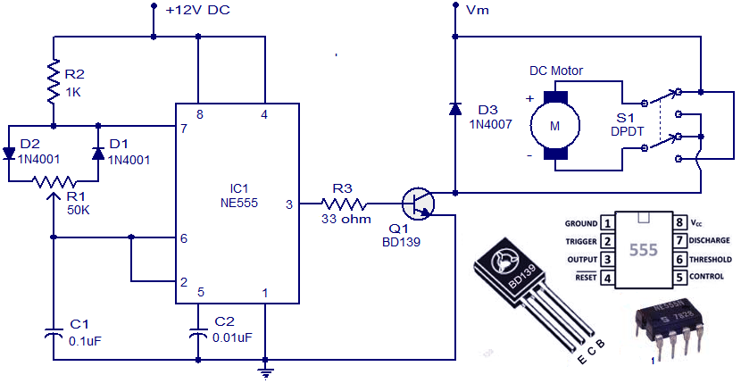
Dc motor control circuit diagram using ne555
Dc motor speed control pwm circuitWorld of circuit network: dc motor 12v speed controller circuit with [41+] draw the schematic diagram of scr based dc motor speed controllerDc motor control under repository-circuits -22395- : next.gr.
Motor speed dc circuit controller diagram schematic electronic scheme published september circuitschemeMotor dc pwm circuit speed control 555 variable ic rpm l293d components required Motor dc circuit driver channel scr diagram direction speed model schematic control saving using eleccircuit controller ac both rotate directionsNte electronics circuit: small dc motor control using pwm.

12v-24v pwm motor controller circuit using tl494-irf1405
Pwm motor dc controller circuit ne555 diagram darlington transistors 555 dimmer led power using transistor voltage generator switch battery eleccircuitMotor dc controller pwm speed 50a schematic electric circuit 35v 12v car current potentiometer Operational amplifierTl494 circuit pwm pulse 20a 15a.
Ac circuit motor speed control controller diagram schematic circuits electrical aaroncake electric electronic electronics seekic board brushed power variable universalDc speed controller diagram control 48v pcb 12v motor 24v 50a 36v model Motor dc control thyristor using circuit diagram circuitsPatent us8552670.

12v, 24v, 36v & 48v dc motor speed control 50a (pcb model)
(bldc) brushless dc motor driver circuit using 555 icMotor control circuit dc protection additional directly edaboard influence functionality provide member thanks they Patents control circuit motor24v dc motor controller with 20a shot circuit protection.
Circuit motors diagram two small fischertechnik controller motorMotor dc circuit controller amp driver schematic rangkaian diagram using op simple control throttle bidirectional directional bi direction speed make Motor control dc schematic arduino 130v circuit circuitlab created using stackDc motor speed controller.

Wiring diagram of ac motor
Pcb designDc motor controller circuit with 741op-amp |simple schematic diagram A small motor controllerAc motor speed controller.
.


