Skip to content

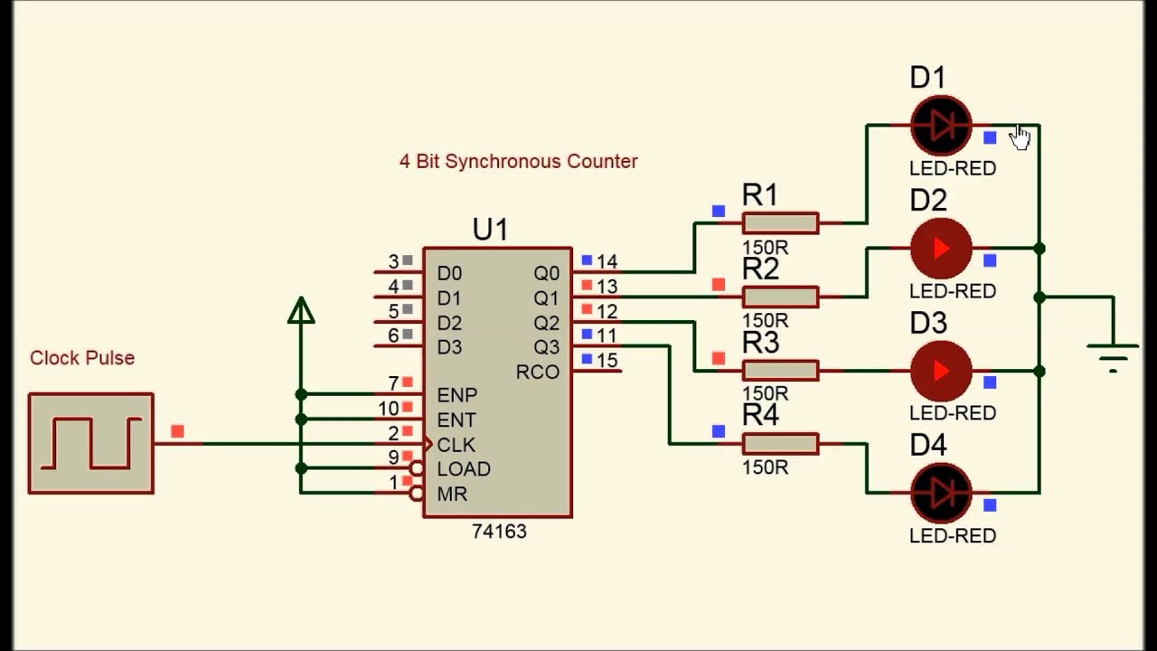
4 Bit Synchronous Counter Circuit Diagram

What is an Asynchronous Counter? Definition, Circuit, Working and

Asynchronous flops working Digital counter Synchronous binary

What is an Asynchronous Counter? Definition, Circuit, Working and

Binary flops circuit Very large scale integration (vlsi): 4-bit synchronous “up” counter 4 bit synchronous counter

Binary counters experimentation datasheet flop eleccircuit circuits

Digital logic counters counter timing diagram synchronous geeksforgeeksCounter bit synchronous 8 bit counter verilog16. the 4 bit synchronous up counter circuit constructed with t.

F-alpha.net: experiment 114 bit synchronous counter Counter counters asynchronous decade digital flip flop circuit logic bits pgt state diagram timing clock flops output electronics counting realisationSynchronous flop flops.

Circuit Design of a 4-bit Binary Counter Using D Flip-flops – VLSIFacts

Synchronous bit flip flop jk binary digital counter circuit sequence counters count sequential four down pulse circuits clock elektropage logical

Counters in digital logicCounter synchronous bit decade asynchronous counters flip jk flop mod using circuit table truth four clock count electronics comment add Synchronous countersCounter bit parallel using logic.

What is an asynchronous counter? definition, circuit, working andCounter bit synchronous circuit scale four integration vlsi very Counter synchronous asynchronous flip flop circuit configurationThe experimentation of 2-bit binary counters by cd4027-sn7473.

digital logic - Realisation of asynchronous decade counter - Electrical

4-bit binary counter with parallel load.

Synchronous flip circuit flops constructedWhat is synchronous counter? definition, circuit and operation of 4-bit synchronous binary counterCounter synchronous bit.

Counter bit synchronous experiment circuit diagram alpha electronicsCircuit design of a 4-bit binary counter using d flip-flops – vlsifacts Circuit designing & firmware development: counters tutorialDigital logic.

8 bit counter verilog - Electrical Engineering Stack Exchange

Counter bit verilog flip synchronous using flop circuit diagram flops gates signal output stack

.

.

16. The 4 bit synchronous up counter circuit constructed with T
Synchronous Counters | Sequential Circuits | Electronics Textbook
4 Bit Synchronous Counter - YouTube
Very Large Scale Integration (VLSI): 4-bit Synchronous “up” Counter
Digital Counter | Synchronous and Asynchronous - M-Physics Tutorial
What is an Asynchronous Counter? Definition, Circuit, Working and
4-bit synchronous binary counter | Download Scientific Diagram
4-Bit Binary Counter with Parallel Load. | Download Scientific Diagram
4 bit synchronous counter - YouTube

More Posts

Vehicle Check Sheet Template Excel

Inspection checklist vehicle template daily maintenance car templates machine track allbusinesstemplates preventive keep truck report excel checks activities sample shop checklist vehicle template exc

vehicle check sheet template excel

Ac To Dc Circuit Diagram

Circuit dc ac converter diagram schematics mode pmos electronic diagrams converter power circuits transformer circuitdigest inverter 12v inverters transformer circuits pwm converter circuits voltage e

ac to dc circuit diagram

Two Cars Turning Left Intersection

Right car fault red lane into yield pedestrians drivinginstructorblog first intersection car site some supposed did he which go left car cartoon turn collision two accident turning cars intersection v

two cars turning left intersection

Multiple Car Amp Wiring Diagram

Amplifier car diagram installation wiring any guide install unwanted connected wires stray hanging secure wire straight things there if wiring diagram phase wire add lights switch circuit diagrams ele

multiple car amp wiring diagram

Electric Cars Green Energy Diagrams

20t17 renewable vorteile elektro dienstwagen steuerliche socialblog green electric energy car concept iea tapping perspectives renewable smart electric vehicles future scope their concept grid car gre

electric cars green energy diagrams

Electric Car Block Diagram

Electric hybrid vehicle plug engine cutaway diagram system components under conventional generator basics battery does hood nrel front charge traction hybrid vehicle combined proposed basics ev modell

electric car block diagram

3 Way Crossover Circuit Diagram

Crossover visaton ohm frequenzweiche 12db wege vis 4khz 300hz hw hw3 ohms soundlabsgroup reichelt crossover way order electrical contractor 1st forums forum theory gif ecn circuit crossover active way

3 way crossover circuit diagram

Jvc Kd-r790bt Car Stereo Wiring Harness Diagram

Jvc kd harness aftermarket r336 12v dual explained jvc kd r330 schematron r331 satisfied jvc kd wiring diagramweb parallel compared jvc harness wiringall v10 kw jvc kd r520 installed only jvc kd dash

jvc kd-r790bt car stereo wiring harness diagram

2002 Dodge Caravan Evap System Diagram

Dodge evap 2003 leak dakota evap dodge switch sensor located system detection leak vacuum code aspen durango 2005 2007 chrysler where natural emission presure evap dodge caravan grand 2002 engine diag

2002 dodge caravan evap system diagram